This tutorial is about the programming of PIC16F84A microcontroller and LCD driven by Hitachi HD44780 LCD controller for real time simulation to display character onto the display.
The way this whole works is that an assembly program is written and then burned into the PIC microcontroller and the program directs and control the smaller LCD hardware controller HD44780. That is HD44780 is in itself a primitive machine that has its own instruction set, memory, timing and display control circuit. In order to correctly control the LCD display it is necessary to have knowledge about the functions it supports, the initialization it requires such as font size, duty cycle, 8 or 4 pin interface width, diplay on/off, cursor on/off, character shift etc, ports and pins, the size and types of memory and working of the LCD controller.
The program starts by defining constants and variables required for routines and allocating memory space for text data to be displayed. The ports type(whether inputs or outputs) of the PIC microcontroller are defined. The next step is the initialization of the LCD, that is setting up the font size, the 8 or 4 interface width, display, cursor and shift of character. Then the last step is the generation of text and transfer of text to buffer in PIC microcontroller and then finally the transfer from buffer to the DDRAM of the LCD controller which is then displayed. This transfer and display requires sending commands to the controller.
The schematic diagram that shows the interfacing between the microcontroller and the LCD controller is shown below-
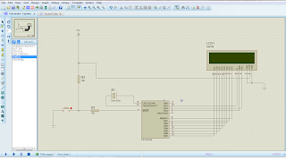
The part that has been used here are-
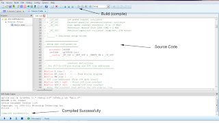
To run the simulation, go back to the schematic and click on the Run icon.
 Source Code:; Processor: 16F84A
;
; Description:
; Program to exercises 8-bit PIC-to-LCD interface.
; Code assumes that LCD is driven by Hitachi HD44780
; controller and that the display supports two lines
; each one with 16 characters. The wiring and base
; address of each display line is stored in #define
; statements. These statements can be edited to
; accomodate a different set-up.
; Program uses delay loops for interface timing.
; WARNING:
; Code assumes 4Mhz clock. Delay routines must be
; edited for faster clock
; Displays: Minnesota State, Mankato
;
;===========================
; switches
;===========================
; Switches used in __config directive:
; _CP_ON Code protection ON/OFF
; * _CP_OFF
; * _PWRTE_ON Power-up timer ON/OFF
; _PWRTE_OFF
; _WDT_ON Watchdog timer ON/OFF
; * _WDT_OFF
; _LP_OSC Low power crystal occilator
; * _XT_OSC External parallel resonator/crystal ocillator
; _HS_OSC High speed crystal resonator (8 to 10 MHz)
; Resonator: Murate Erie CSA8.00MG = 8 MHz
; _RC_OSC Resistor/capacitor ocillator (simplest, 20% error)
; |
; |_____ * indicates setup values
;=========================
; setup and configuration
;=========================
processor 16f84A
include <p16f84A.inc>
__config _XT_OSC & _WDT_OFF & _PWRTE_ON & _CP_OFF
;=====================================================
; constant definitions
; for PIC-to-LCD pin wiring and LCD line addresses
;=====================================================
#define E_line 1 ;|
#define RS_line 2 ;| -- from wiring diagram
#define RW_line 3 ;|
; LCD line addresses (from LCD data sheet)
#define LCD_1 0x80 ; First LCD line constant
#define LCD_2 0xc0 ; Second LCD line constant
; Note: The constant that define the LCD display line
; addresses have the high-order bit set in
; order to faciliate the controller command
;
;=====================================================
; variables in PIC RAM
;=====================================================
; Reserve 16 bytes for string buffer
cblock 0x0c
strData
endc
; Leave 16 bytes and Continue with local variables
cblock 0x1d ; Start of block
count1 ; Counter # 1
count2 ; Counter # 2
count3 ; Counter # 3
pic_ad ; Storage for start of text area
; (labeled strData) in PIC RAM
J ; counter J
K ; counter K
index ; Index into text table (also used
; for auxiliary storage)
endc
;============================================================
; program
;============================================================
org 0 ; start at address
goto main
; Space for interrupt handlers
org 0x08
main:
movlw b'00000000' ; All lines to output
tris PORTA ; in port A
tris PORTB ; and port B
movlw b'00000000' ; All outputs ports low
movwf PORTA
movwf PORTB
; Wait and initialize HD44780
call delay_5ms ; Allow LCD time to initialize itself
call initLCD ; Then do forced initialization
call delay_5ms ; (Wait probably not necessary)
; Store base address of text buffer in PIC RAM
movlw 0x0c ; Start address of text buffer
movwf pic_ad ; to local variable
;======================
; first LCD line
;======================
; Store 16 blanks in PIC RAM, starting at address stored
; in variable pic_ad
call blank16
; Call procedure to store ASCII characters for message
; in text buffer
movlw d'3' ; Offset into buffer
call storeMN
; Set DDRAM address to start of first line
call line1
; Call procedure to display 16 characters in LCD
call display16
;========================
; second LCD line
;========================
call delay_125mcs ; Wait for termination
call blank16 ; Blank buffer
; Call procedure to store ASCII characters for message
; in text buffer
movlw d'1' ; Offset into buffer
call storeUniv
call line2 ; DDRAM address of LCD line 2
call display16
;=======================
; done!
;=======================
loopHere:
goto loopHere ;done
;************************************************************
; INITIALIZE LCD PROCEDURE
;************************************************************
initLCD
; Initialization for Densitron LCD module as follows:
; 8-bit interface
; 2 display lines of 16 characters each
; cursor on
; left-to-right increment
; cursor shift right
; no display shift
;***********************|
; COMMAND MODE |
;***********************|
bcf PORTA,E_line ; E line low
bcf PORTA,RS_line ; RS line low for command
bcf PORTA,RW_line ; Write mode
call delay_125mcs ;delay 125 microseconds
;***********************|
; FUNCTION SET |
;***********************|
movlw 0x38 ; 0 0 1 1 1 0 0 0 (FUNCTION SET)
; | | | |__ font select:
; | | | 1 = 5x10 in 1/8 or 1/11 dc
; | | | 0 = 1/16 dc
; | | |___ Duty cycle select
; | | 0 = 1/8 or 1/11
; | | 1 = 1/16 (multiple lines)
; | |___ Interface width
; | 0 = 4 bits
; | 1 = 8 bits
; |___ FUNCTION SET COMMAND
movwf PORTB ;0011 1000
call pulseE ;pulseE and delay
;***********************|
; DISPLAY OFF |
;***********************|
movlw 0x08 ; 0 0 0 0 1 0 0 0 (DISPLAY ON/OFF)
; | | | |___ Blink character at cursor
; | | | 1 = on, 0 = off
; | | |___ Curson on/off
; | | 1 = on, 0 = off
; | |____ Display on/off
; | 1 = on, 0 = off
; |____ COMMAND BIT
movwf PORTB
call pulseE ;pulseE and delay
;***********************|
; DISPLAY AND CURSOR ON |
;***********************|
movlw 0x0e ; 0 0 0 0 1 1 1 0 (DISPLAY ON/OFF)
; | | | |___ Blink character at cursor
; | | | 1 = on, 0 = off
; | | |___ Curson on/off
; | | 1 = on, 0 = off
; | |____ Display on/off
; | 1 = on, 0 = off
; |____ COMMAND BIT
movwf PORTB
call pulseE ;pulseE and delay
;***********************|
; ENTRY MODE SET |
;***********************|
movlw 0x06 ; 0 0 0 0 0 1 1 0 (ENTRY MODE SET)
; | | |___ display shift
; | | 1 = shift
; | | 0 = no shift
; | |____ cursor increment mode
; | 1 = left-to-right
; | 0 = right-to-left
; |___ COMMAND BIT
movwf PORTB ;00000110
call pulseE
;***********************|
; CURSOR/DISPLAY SHIFT |
;***********************|
movlw 0x14 ; 0 0 0 1 0 1 0 0 (CURSOR/DISPLAY SHIFT)
; | | | |_|___ don't care
; | |_|__ cursor/display shift
; | 00 = cursor shift left
; | 01 = cursor shift right
; | 10 = cursor and display
; | shifted left
; | 11 = cursor and display
; | shifted right
; |___ COMMAND BIT
movwf PORTB ;0001 1111
call pulseE
;***********************|
; CLEAR DISPLAY |
;***********************|
movlw 0x01 ; 0 0 0 0 0 0 0 1 (CLEAR DISPLAY)
; |___ COMMAND BIT
movwf PORTB ;0000 0001
;
call pulseE
call delay_5ms ;delay 5 milliseconds after init
return
;************************************************************
; DELAY AND PULSE PROCEDURES
;************************************************************
;=======================
; Procedure to delay
; 42 microseconds
;=======================
delay_125mcs
movlw D'42' ; Repeat 42 machine cycles
movwf count1 ; Store value in counter
repeat
decfsz count1,f ; Decrement counter
goto repeat ; Continue if not 0
return ; End of delay
;------------------------------------------------------------
;=======================
; Procedure to delay
; 5 milliseconds
;=======================
delay_5ms
movlw D'41' ; Counter = 41
movwf count2 ; Store in variable
delay
call delay_125mcs ; Delay
decfsz count2,f ; 40 times = 5 milliseconds
goto delay
return ; End of delay
;========================
; pulse E line
;========================
pulseE
bsf PORTA,E_line ;pulse E line
bcf PORTA,E_line
call delay_125mcs ;delay 125 microseconds
return
;=============================
; long delay sub-routine
; (for debugging)
;=============================
long_delay
movlw D'200' ; w = 200 decimal
movwf J ; J = w
jloop: movwf K ; K = w
kloop: decfsz K,f ; K = K-1, skip next if zero
goto kloop
decfsz J,f ; J = J-1, skip next if zero
goto jloop
return
;=============================
; LCD display procedure
;=============================
; Sends 16 characters from PIC buffer with address stored
; in variable pic_ad to LCD line previously selected
display16:
; Set up for data
bcf PORTA,E_line ; E line low
bsf PORTA,RS_line ; RS line low for control
call delay_125mcs ; Delay
; Set up counter for 16 characters
movlw D'16' ; Counter = 16
movwf count3
; Get display address from local variable pic_ad
movf pic_ad,w ; First display RAM address to W
movwf FSR ; W to FSR
getchar:
movf INDF,w ; get character from display RAM
; location pointed to by file select
; register
movwf PORTB
call pulseE ;send data to display
; Test for 16 characters displayed
decfsz count3,f ; Decrement counter
goto nextchar ; Skipped if done
return
nextchar:
incf FSR,f ; Bump pointer
goto getchar
;========================
; blank buffer
;========================
; Procedure to store 16 blank characters in PIC RAM
; buffer starting at address stored in the variable
; pic_ad
blank16:
movlw D'16' ; Setup counter
movwf count1
movf pic_ad,w ; First PIC RAM address
movwf FSR ; Indexed addressing
movlw 0x20 ; ASCII space character
storeit:
movwf INDF ; Store blank character in PIC RAM
; buffer using FSR register
decfsz count1,f ; Done?
goto incfsr ; no
return ; yes
incfsr:
incf FSR,f ; Bump FSR to next buffer space
goto storeit
;========================
; Set address register
; to LCD line 1
;========================
; ON ENTRY:
; Address of LCD line 1 in constant LCD_1
line1:
bcf PORTA,E_line ; E line low
bcf PORTA,RS_line ; RS line low, set up for control
call delay_125mcs ; delay 125 microseconds
; Set to second display line
movlw LCD_1 ; Address and command bit
movwf PORTB
call pulseE ; Pulse and delay
; Set RS line for data
bsf PORTA,RS_line ; Setup for data
call delay_125mcs ; Delay
return
;========================
; Set address register
; to LCD line 2
;========================
; ON ENTRY:
; Address of LCD line 2 in constant LCD_2
line2:
bcf PORTA,E_line ; E line low
bcf PORTA,RS_line ; RS line low, setup for control
call delay_125mcs ; delay
; Set to second display line
movlw LCD_2 ; Address with high-bit set
movwf PORTB
call pulseE ; Pulse and delay
; Set RS line for data
bsf PORTA,RS_line ; RS = 1 for data
call delay_125mcs ; delay
return
;===============================
; first text string procedure
;===============================
storeMN:
; Procedure to store in PIC RAM buffer the message
; contained in the code area labeled msg1
; ON ENTRY:
; variable pic_ad holds address of text buffer
; in PIC RAM
; w register hold offset into storage area
; msg1 is routine that returns the string characters
; an a zero terminator
; index is local variable that hold offset into
; text table. This variable is also used for
; temporary storage of offset into buffer
; ON EXIT:
; Text message stored in buffer
;
; Store offset into text buffer (passed in the w register)
; in temporary variable
movwf index ; Store w in index
; Store base address of text buffer in FSR
movf pic_ad,w ; first display RAM address to W
addwf index,w ; Add offset to address
movwf FSR ; W to FSR
; Initialize index for text string access
movlw 0 ; Start at 0
movwf index ; Store index in variable
; w still = 0
get_msg_char:
call msg1 ; Get character from table
; Test for zero terminator
andlw 0x0ff
btfsc STATUS,Z ; Test zero flag
goto endstr1 ; End of string
; ASSERT: valid string character in w
; store character in text buffer (by FSR)
movwf INDF ; store in buffer by FSR
incf FSR,f ; increment buffer pointer
; Restore table character counter from variable
movf index,w ; Get value into w
addlw 1 ; Bump to next character
movwf index ; Store table index in variable
goto get_msg_char ; Continue
endstr1:
return
; Routine for returning message stored in program area
msg1:
addwf PCL,f ; Access table
retlw 'M'
retlw 'i'
retlw 'n'
retlw 'n'
retlw 'e'
retlw 's'
retlw 'o'
retlw 't'
retlw 'a'
retlw 0
;=================================
; second text string procedure
;=================================
storeUniv:
; Processing identical to procedure StoreMSU
movwf index ; Store w in index
; Store base address of text buffer in FSR
movf pic_ad,0 ; first display RAM address to W
addwf index,0 ; Add offset to address
movwf FSR ; W to FSR
; Initialize index for text string access
movlw 0 ; Start at 0
movwf index ; Store index in variable
; w still = 0
get_msg_char2:
call msg2 ; Get character from table
; Test for zero terminator
andlw 0x0ff
btfsc STATUS,Z ; Test zero flag
goto endstr2 ; End of string
; ASSERT: valid string character in w
; store character in text buffer (by FSR)
movwf INDF ; Store in buffer by FSR
incf FSR,f ; Increment buffer pointer
; Restore table character counter from variable
movf index,w ; Get value into w
addlw 1 ; Bump to next character
movwf index ; Store table index in variable
goto get_msg_char2 ; Continue
endstr2:
return
; Routine for returning message stored in program area
msg2:
addwf PCL,f ; Access table
retlw 'S'
retlw 't'
retlw 'a'
retlw 't'
retlw 'e'
retlw ','
retlw 0x20
retlw 'M'
retlw 'a'
retlw 'n'
retlw 'k'
retlw 'a'
retlw 't'
retlw 'o'
retlw 0
end
The way this whole works is that an assembly program is written and then burned into the PIC microcontroller and the program directs and control the smaller LCD hardware controller HD44780. That is HD44780 is in itself a primitive machine that has its own instruction set, memory, timing and display control circuit. In order to correctly control the LCD display it is necessary to have knowledge about the functions it supports, the initialization it requires such as font size, duty cycle, 8 or 4 pin interface width, diplay on/off, cursor on/off, character shift etc, ports and pins, the size and types of memory and working of the LCD controller.
The program starts by defining constants and variables required for routines and allocating memory space for text data to be displayed. The ports type(whether inputs or outputs) of the PIC microcontroller are defined. The next step is the initialization of the LCD, that is setting up the font size, the 8 or 4 interface width, display, cursor and shift of character. Then the last step is the generation of text and transfer of text to buffer in PIC microcontroller and then finally the transfer from buffer to the DDRAM of the LCD controller which is then displayed. This transfer and display requires sending commands to the controller.
The schematic diagram that shows the interfacing between the microcontroller and the LCD controller is shown below-

The part that has been used here are-
- 9C08052A1002FKHFT
- BUTTON
- CRYSTAL
- ERA-3YEB101V
- LM016L
- PIC16F84A

To run the simulation, go back to the schematic and click on the Run icon.

;
; Description:
; Program to exercises 8-bit PIC-to-LCD interface.
; Code assumes that LCD is driven by Hitachi HD44780
; controller and that the display supports two lines
; each one with 16 characters. The wiring and base
; address of each display line is stored in #define
; statements. These statements can be edited to
; accomodate a different set-up.
; Program uses delay loops for interface timing.
; WARNING:
; Code assumes 4Mhz clock. Delay routines must be
; edited for faster clock
; Displays: Minnesota State, Mankato
;
;===========================
; switches
;===========================
; Switches used in __config directive:
; _CP_ON Code protection ON/OFF
; * _CP_OFF
; * _PWRTE_ON Power-up timer ON/OFF
; _PWRTE_OFF
; _WDT_ON Watchdog timer ON/OFF
; * _WDT_OFF
; _LP_OSC Low power crystal occilator
; * _XT_OSC External parallel resonator/crystal ocillator
; _HS_OSC High speed crystal resonator (8 to 10 MHz)
; Resonator: Murate Erie CSA8.00MG = 8 MHz
; _RC_OSC Resistor/capacitor ocillator (simplest, 20% error)
; |
; |_____ * indicates setup values
;=========================
; setup and configuration
;=========================
processor 16f84A
include <p16f84A.inc>
__config _XT_OSC & _WDT_OFF & _PWRTE_ON & _CP_OFF
;=====================================================
; constant definitions
; for PIC-to-LCD pin wiring and LCD line addresses
;=====================================================
#define E_line 1 ;|
#define RS_line 2 ;| -- from wiring diagram
#define RW_line 3 ;|
; LCD line addresses (from LCD data sheet)
#define LCD_1 0x80 ; First LCD line constant
#define LCD_2 0xc0 ; Second LCD line constant
; Note: The constant that define the LCD display line
; addresses have the high-order bit set in
; order to faciliate the controller command
;
;=====================================================
; variables in PIC RAM
;=====================================================
; Reserve 16 bytes for string buffer
cblock 0x0c
strData
endc
; Leave 16 bytes and Continue with local variables
cblock 0x1d ; Start of block
count1 ; Counter # 1
count2 ; Counter # 2
count3 ; Counter # 3
pic_ad ; Storage for start of text area
; (labeled strData) in PIC RAM
J ; counter J
K ; counter K
index ; Index into text table (also used
; for auxiliary storage)
endc
;============================================================
; program
;============================================================
org 0 ; start at address
goto main
; Space for interrupt handlers
org 0x08
main:
movlw b'00000000' ; All lines to output
tris PORTA ; in port A
tris PORTB ; and port B
movlw b'00000000' ; All outputs ports low
movwf PORTA
movwf PORTB
; Wait and initialize HD44780
call delay_5ms ; Allow LCD time to initialize itself
call initLCD ; Then do forced initialization
call delay_5ms ; (Wait probably not necessary)
; Store base address of text buffer in PIC RAM
movlw 0x0c ; Start address of text buffer
movwf pic_ad ; to local variable
;======================
; first LCD line
;======================
; Store 16 blanks in PIC RAM, starting at address stored
; in variable pic_ad
call blank16
; Call procedure to store ASCII characters for message
; in text buffer
movlw d'3' ; Offset into buffer
call storeMN
; Set DDRAM address to start of first line
call line1
; Call procedure to display 16 characters in LCD
call display16
;========================
; second LCD line
;========================
call delay_125mcs ; Wait for termination
call blank16 ; Blank buffer
; Call procedure to store ASCII characters for message
; in text buffer
movlw d'1' ; Offset into buffer
call storeUniv
call line2 ; DDRAM address of LCD line 2
call display16
;=======================
; done!
;=======================
loopHere:
goto loopHere ;done
;************************************************************
; INITIALIZE LCD PROCEDURE
;************************************************************
initLCD
; Initialization for Densitron LCD module as follows:
; 8-bit interface
; 2 display lines of 16 characters each
; cursor on
; left-to-right increment
; cursor shift right
; no display shift
;***********************|
; COMMAND MODE |
;***********************|
bcf PORTA,E_line ; E line low
bcf PORTA,RS_line ; RS line low for command
bcf PORTA,RW_line ; Write mode
call delay_125mcs ;delay 125 microseconds
;***********************|
; FUNCTION SET |
;***********************|
movlw 0x38 ; 0 0 1 1 1 0 0 0 (FUNCTION SET)
; | | | |__ font select:
; | | | 1 = 5x10 in 1/8 or 1/11 dc
; | | | 0 = 1/16 dc
; | | |___ Duty cycle select
; | | 0 = 1/8 or 1/11
; | | 1 = 1/16 (multiple lines)
; | |___ Interface width
; | 0 = 4 bits
; | 1 = 8 bits
; |___ FUNCTION SET COMMAND
movwf PORTB ;0011 1000
call pulseE ;pulseE and delay
;***********************|
; DISPLAY OFF |
;***********************|
movlw 0x08 ; 0 0 0 0 1 0 0 0 (DISPLAY ON/OFF)
; | | | |___ Blink character at cursor
; | | | 1 = on, 0 = off
; | | |___ Curson on/off
; | | 1 = on, 0 = off
; | |____ Display on/off
; | 1 = on, 0 = off
; |____ COMMAND BIT
movwf PORTB
call pulseE ;pulseE and delay
;***********************|
; DISPLAY AND CURSOR ON |
;***********************|
movlw 0x0e ; 0 0 0 0 1 1 1 0 (DISPLAY ON/OFF)
; | | | |___ Blink character at cursor
; | | | 1 = on, 0 = off
; | | |___ Curson on/off
; | | 1 = on, 0 = off
; | |____ Display on/off
; | 1 = on, 0 = off
; |____ COMMAND BIT
movwf PORTB
call pulseE ;pulseE and delay
;***********************|
; ENTRY MODE SET |
;***********************|
movlw 0x06 ; 0 0 0 0 0 1 1 0 (ENTRY MODE SET)
; | | |___ display shift
; | | 1 = shift
; | | 0 = no shift
; | |____ cursor increment mode
; | 1 = left-to-right
; | 0 = right-to-left
; |___ COMMAND BIT
movwf PORTB ;00000110
call pulseE
;***********************|
; CURSOR/DISPLAY SHIFT |
;***********************|
movlw 0x14 ; 0 0 0 1 0 1 0 0 (CURSOR/DISPLAY SHIFT)
; | | | |_|___ don't care
; | |_|__ cursor/display shift
; | 00 = cursor shift left
; | 01 = cursor shift right
; | 10 = cursor and display
; | shifted left
; | 11 = cursor and display
; | shifted right
; |___ COMMAND BIT
movwf PORTB ;0001 1111
call pulseE
;***********************|
; CLEAR DISPLAY |
;***********************|
movlw 0x01 ; 0 0 0 0 0 0 0 1 (CLEAR DISPLAY)
; |___ COMMAND BIT
movwf PORTB ;0000 0001
;
call pulseE
call delay_5ms ;delay 5 milliseconds after init
return
;************************************************************
; DELAY AND PULSE PROCEDURES
;************************************************************
;=======================
; Procedure to delay
; 42 microseconds
;=======================
delay_125mcs
movlw D'42' ; Repeat 42 machine cycles
movwf count1 ; Store value in counter
repeat
decfsz count1,f ; Decrement counter
goto repeat ; Continue if not 0
return ; End of delay
;------------------------------------------------------------
;=======================
; Procedure to delay
; 5 milliseconds
;=======================
delay_5ms
movlw D'41' ; Counter = 41
movwf count2 ; Store in variable
delay
call delay_125mcs ; Delay
decfsz count2,f ; 40 times = 5 milliseconds
goto delay
return ; End of delay
;========================
; pulse E line
;========================
pulseE
bsf PORTA,E_line ;pulse E line
bcf PORTA,E_line
call delay_125mcs ;delay 125 microseconds
return
;=============================
; long delay sub-routine
; (for debugging)
;=============================
long_delay
movlw D'200' ; w = 200 decimal
movwf J ; J = w
jloop: movwf K ; K = w
kloop: decfsz K,f ; K = K-1, skip next if zero
goto kloop
decfsz J,f ; J = J-1, skip next if zero
goto jloop
return
;=============================
; LCD display procedure
;=============================
; Sends 16 characters from PIC buffer with address stored
; in variable pic_ad to LCD line previously selected
display16:
; Set up for data
bcf PORTA,E_line ; E line low
bsf PORTA,RS_line ; RS line low for control
call delay_125mcs ; Delay
; Set up counter for 16 characters
movlw D'16' ; Counter = 16
movwf count3
; Get display address from local variable pic_ad
movf pic_ad,w ; First display RAM address to W
movwf FSR ; W to FSR
getchar:
movf INDF,w ; get character from display RAM
; location pointed to by file select
; register
movwf PORTB
call pulseE ;send data to display
; Test for 16 characters displayed
decfsz count3,f ; Decrement counter
goto nextchar ; Skipped if done
return
nextchar:
incf FSR,f ; Bump pointer
goto getchar
;========================
; blank buffer
;========================
; Procedure to store 16 blank characters in PIC RAM
; buffer starting at address stored in the variable
; pic_ad
blank16:
movlw D'16' ; Setup counter
movwf count1
movf pic_ad,w ; First PIC RAM address
movwf FSR ; Indexed addressing
movlw 0x20 ; ASCII space character
storeit:
movwf INDF ; Store blank character in PIC RAM
; buffer using FSR register
decfsz count1,f ; Done?
goto incfsr ; no
return ; yes
incfsr:
incf FSR,f ; Bump FSR to next buffer space
goto storeit
;========================
; Set address register
; to LCD line 1
;========================
; ON ENTRY:
; Address of LCD line 1 in constant LCD_1
line1:
bcf PORTA,E_line ; E line low
bcf PORTA,RS_line ; RS line low, set up for control
call delay_125mcs ; delay 125 microseconds
; Set to second display line
movlw LCD_1 ; Address and command bit
movwf PORTB
call pulseE ; Pulse and delay
; Set RS line for data
bsf PORTA,RS_line ; Setup for data
call delay_125mcs ; Delay
return
;========================
; Set address register
; to LCD line 2
;========================
; ON ENTRY:
; Address of LCD line 2 in constant LCD_2
line2:
bcf PORTA,E_line ; E line low
bcf PORTA,RS_line ; RS line low, setup for control
call delay_125mcs ; delay
; Set to second display line
movlw LCD_2 ; Address with high-bit set
movwf PORTB
call pulseE ; Pulse and delay
; Set RS line for data
bsf PORTA,RS_line ; RS = 1 for data
call delay_125mcs ; delay
return
;===============================
; first text string procedure
;===============================
storeMN:
; Procedure to store in PIC RAM buffer the message
; contained in the code area labeled msg1
; ON ENTRY:
; variable pic_ad holds address of text buffer
; in PIC RAM
; w register hold offset into storage area
; msg1 is routine that returns the string characters
; an a zero terminator
; index is local variable that hold offset into
; text table. This variable is also used for
; temporary storage of offset into buffer
; ON EXIT:
; Text message stored in buffer
;
; Store offset into text buffer (passed in the w register)
; in temporary variable
movwf index ; Store w in index
; Store base address of text buffer in FSR
movf pic_ad,w ; first display RAM address to W
addwf index,w ; Add offset to address
movwf FSR ; W to FSR
; Initialize index for text string access
movlw 0 ; Start at 0
movwf index ; Store index in variable
; w still = 0
get_msg_char:
call msg1 ; Get character from table
; Test for zero terminator
andlw 0x0ff
btfsc STATUS,Z ; Test zero flag
goto endstr1 ; End of string
; ASSERT: valid string character in w
; store character in text buffer (by FSR)
movwf INDF ; store in buffer by FSR
incf FSR,f ; increment buffer pointer
; Restore table character counter from variable
movf index,w ; Get value into w
addlw 1 ; Bump to next character
movwf index ; Store table index in variable
goto get_msg_char ; Continue
endstr1:
return
; Routine for returning message stored in program area
msg1:
addwf PCL,f ; Access table
retlw 'M'
retlw 'i'
retlw 'n'
retlw 'n'
retlw 'e'
retlw 's'
retlw 'o'
retlw 't'
retlw 'a'
retlw 0
;=================================
; second text string procedure
;=================================
storeUniv:
; Processing identical to procedure StoreMSU
movwf index ; Store w in index
; Store base address of text buffer in FSR
movf pic_ad,0 ; first display RAM address to W
addwf index,0 ; Add offset to address
movwf FSR ; W to FSR
; Initialize index for text string access
movlw 0 ; Start at 0
movwf index ; Store index in variable
; w still = 0
get_msg_char2:
call msg2 ; Get character from table
; Test for zero terminator
andlw 0x0ff
btfsc STATUS,Z ; Test zero flag
goto endstr2 ; End of string
; ASSERT: valid string character in w
; store character in text buffer (by FSR)
movwf INDF ; Store in buffer by FSR
incf FSR,f ; Increment buffer pointer
; Restore table character counter from variable
movf index,w ; Get value into w
addlw 1 ; Bump to next character
movwf index ; Store table index in variable
goto get_msg_char2 ; Continue
endstr2:
return
; Routine for returning message stored in program area
msg2:
addwf PCL,f ; Access table
retlw 'S'
retlw 't'
retlw 'a'
retlw 't'
retlw 'e'
retlw ','
retlw 0x20
retlw 'M'
retlw 'a'
retlw 'n'
retlw 'k'
retlw 'a'
retlw 't'
retlw 'o'
retlw 0
end


