This is an introduction tutorial on Labview which shows how to use enter the input and output controls into the front panel and the functional parts in the block diagram panel. After having placed the required controls and elements we perform simulation to get output.
Readers may acquire
Labview download student, visit the blog post.
The Labview can consist of two panel- Front Panel and Block Diagram Panel. The front panel is used to place users input/output controls blocks and the block diagram panel is where you put the the actual algorithm implementation using functional blocks.
The picture below shows these two panels-
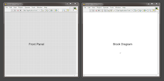 |
| Picture: Labview front and block diagram panel |
Here we give an simple example on how to set up labview to perform XOR of two sequence of binary data sequence.
To do this right click on the Front panel and select Array,Matrix & Cluster then Array as shown
Once it is single clicked it is attached automatically attached to the mouse cursor. Place the input array in suitable location in the front panel workspace. As it is placed on the front panel the corresponding functional block is added in the block diagram panel as shown-
Now place another two such arrays-
Now to define input and output we have to place numeric input and output(indicator) inside the array. To do this, right click and select Numeric>Numeric Control as shown below and drop it inside the first array box.
Now drag the array so that it has 8 rows-
Repeat the same process for Array2.
For the Array3 we need to insert Numeric Indicator instead of Numeric Control because it is the output . Insert the Numeric Indicator into the Array3 as shown-
Change the labels Array, Array2 and Array3 by simple double clicking it and editing to Input A, Input B and Output.
To make more descriptive on what the inputs are doing to get the output, just double click on the space between Input A and Input B and write 'XOR' and write a '=' between the Input B and Output array as shown below. Note that you can increase the Font size using ctrl+=.
We are finished for now with the input/output interface design. Now we will have to add the function XOR in the block diagram panel.
To do this relocate the array blocks in the block diagram that looks something like the one below-
Now right click on the block diagram panel and add the XOR by going to Boolean>Exclusive Or as shown below-
The picture below shows the XOR block in between the input and output-
Now join them with the wires as shown-
Now the entry step is complete and we need to run the simulation. But before running the simulation we need to add the binary digits into the Input A and Input B array in the Front Panel. Enter random binary digits. The following shows an example-
Notice that the output is grayed colored.
Now we are ready for simulation. Click on the 'Run Continuously' icon on the toolbar and we get the output result. This is shown below-
The XOR outputs 0 when both inputs are 1 or 0 and outputs 1 when the inputs are different. As seen from the output the output is XOR of the inputs.
This completes the introduction tutorial of Labview.


