This is a overall tutorial on how to create an integrated library in Altium designer. Integrated library is one unique feature of Altium designer that allows users to have an integrated library of schematic symbol, footprint, simulation model, signal integrity file and 3D view of the component. This way designers can quickly have a unified library of a component instead of having distributed parts in different folder.
There are number of ways to create Integrated Library file(<filename>.IntLib). One of them is to create a new package library(.PkgLib), add the schematic library(.SchLib)with schematic model, footprint library(.PcbLib) with footprint and other files(simulation, signal integrity, 3D) and compile the package library into integrated library file. Thus package lib file is one that binds the various model files into a single integrated library file.
Thus the first step is to create an Integrated library project. To do this follow the steps below-
1. Create a new Integrated Library
New > Project > Integrated Library as shown-

As shown below library package file with default name "Integrated_Library1.LibPkg" will be created in the project navigation bar.

It is good practice to save the project with some identifying name first. Right click on the "Integrated_Library1.LibPkg" and select "Save Project As" as shown-

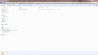
Now provide some name such as "part_name_library" and browse to some location in your drive and click on "save" to save it there.

Now the integrated library project will be saved with the new "part_name_library" name and this change will also be reflected in the project navigation window as shown-

2. Add new schematic library to the integrated library project.
The next step is to add new schematic library to the integrated library project. To do this, right click on the part_name_library.LibPkg and select "Add New to Project" and from there select "Schematic_Library" as shown-
This will add a new schematic library document which will be visible under the part_name_library.LibPkg in the project navigation bar and the schematic editor window is visible-

Now to rename it and save it, right click on the schlib1.SchLib and click on "Save As" and enter some name like "part_sch_library" as shown below-

Now the name has changed as shown below-

Now click on the SCH library tab at the bottom right as shown-

This will bring up the SCH library panel shown below

It is here where we can draw the graphical symbol for the schematic component.
Here we have option to draw a new schematic component or copy and paste existing one. This is a tutorial on how to create an integrated package library rather than creating a new component from the scratch.
For illustration purpose the schematic symbol of 2N3904 is used here. After drawing the schematic NPN symbol for 2N3904 looks like the figure below-

Click on Tool > Rename Component and type in 2N3904. This will change the component name as reflected in the schematic library-

Now the footprint, simulation model, signal integrity and PCB3D file can be added. The footprint and simulation model will be added here. Same process is used to add the signal integrity model file and the PCB3D file.
To add the footprint, click on the "Add Footprint" in the buttom panel as shown-

The PCB Model window will open that allows to select the footprint to attach from the listed footprint or by browsing to the directory where the desired footprint is located. For this tutorial, the footprint TO-92A that is required is located in the same folder as project folder. Browsing and selecting the footprint is shown below-

and then by setting the path for the project folder, the files in the path will be shown-

Select the footprint "2N3904.PcbLib" as shown-


After selecting the footprint the name and description will change-

Click ok and the footprint is now attached to the schematic library part as shown-

Similarly to add the simulation model file, click on the small select buttom near the Add Footprint as shown in figure below and select "Simulation"-
 Then select Simulation-

This brings up the window to select the simulation model file. Click on browse and select the simulation model 2N3904.mdl as shown-
 This bring up the another window where we can check the selected simulation model and confirm. Click OK.

Now the simulation model is also added as shown-

In this way the signal integrity file and the PCB3D file can be added.
Now to compile the package library go to the project. Select and right click the "part_name_library.LibPkg" and click on "Compile Integrated Library part_name_library.LibPkg" as shown-
 The next window ask to save, click on OK to complete the creation of integrated library for the transistor.
After this a folder called ProjectOutputs is created automatically and the newly created Integrated Library File is resides within it as shown-
Now to use the newly created Integrated Library open a schematic sheet and select Part. Browse and add the newly created integrated library. This is as shown-

Place the Component onto the schematic sheet and the component is ready to be used.

This completes the tutorial.
There are number of ways to create Integrated Library file(<filename>.IntLib). One of them is to create a new package library(.PkgLib), add the schematic library(.SchLib)with schematic model, footprint library(.PcbLib) with footprint and other files(simulation, signal integrity, 3D) and compile the package library into integrated library file. Thus package lib file is one that binds the various model files into a single integrated library file.
Thus the first step is to create an Integrated library project. To do this follow the steps below-
1. Create a new Integrated Library
New > Project > Integrated Library as shown-

As shown below library package file with default name "Integrated_Library1.LibPkg" will be created in the project navigation bar.

It is good practice to save the project with some identifying name first. Right click on the "Integrated_Library1.LibPkg" and select "Save Project As" as shown-

Now provide some name such as "part_name_library" and browse to some location in your drive and click on "save" to save it there.

Now the integrated library project will be saved with the new "part_name_library" name and this change will also be reflected in the project navigation window as shown-

2. Add new schematic library to the integrated library project.
The next step is to add new schematic library to the integrated library project. To do this, right click on the part_name_library.LibPkg and select "Add New to Project" and from there select "Schematic_Library" as shown-

This will add a new schematic library document which will be visible under the part_name_library.LibPkg in the project navigation bar and the schematic editor window is visible-

Now to rename it and save it, right click on the schlib1.SchLib and click on "Save As" and enter some name like "part_sch_library" as shown below-

Now the name has changed as shown below-

Now click on the SCH library tab at the bottom right as shown-

This will bring up the SCH library panel shown below

It is here where we can draw the graphical symbol for the schematic component.
Here we have option to draw a new schematic component or copy and paste existing one. This is a tutorial on how to create an integrated package library rather than creating a new component from the scratch.
For illustration purpose the schematic symbol of 2N3904 is used here. After drawing the schematic NPN symbol for 2N3904 looks like the figure below-

Click on Tool > Rename Component and type in 2N3904. This will change the component name as reflected in the schematic library-

Now the footprint, simulation model, signal integrity and PCB3D file can be added. The footprint and simulation model will be added here. Same process is used to add the signal integrity model file and the PCB3D file.
To add the footprint, click on the "Add Footprint" in the buttom panel as shown-

The PCB Model window will open that allows to select the footprint to attach from the listed footprint or by browsing to the directory where the desired footprint is located. For this tutorial, the footprint TO-92A that is required is located in the same folder as project folder. Browsing and selecting the footprint is shown below-

and then by setting the path for the project folder, the files in the path will be shown-

Select the footprint "2N3904.PcbLib" as shown-


After selecting the footprint the name and description will change-

Click ok and the footprint is now attached to the schematic library part as shown-

Similarly to add the simulation model file, click on the small select buttom near the Add Footprint as shown in figure below and select "Simulation"-


This brings up the window to select the simulation model file. Click on browse and select the simulation model 2N3904.mdl as shown-


Now the simulation model is also added as shown-

In this way the signal integrity file and the PCB3D file can be added.
Now to compile the package library go to the project. Select and right click the "part_name_library.LibPkg" and click on "Compile Integrated Library part_name_library.LibPkg" as shown-

After this a folder called ProjectOutputs is created automatically and the newly created Integrated Library File is resides within it as shown-

Now to use the newly created Integrated Library open a schematic sheet and select Part. Browse and add the newly created integrated library. This is as shown-

Place the Component onto the schematic sheet and the component is ready to be used.

This completes the tutorial.
Tidak ada komentar:
Posting Komentar