FM Pre-emphasis and De-empahsis is a technique in FM communication wherein a circuit called pre-emphasis is used at the FM transmitter to emphasis the high frequency components of the message signal before modulation and at the receiver after demodulation and discrimination a circuit called de-emphasis is used to suppress(or de-emphasis) the high frequency components of the message signal that was emphasized at the transmitter. That is the de-emphasis circuit restore the high frequency components. The reason for doing this is to lower the noise power and improve the SNR.
This blog post illustrates the concept and working principle of FM pre-emphasis and de-emphasis used in FM transmitter and receiver with simple circuits constructed in Orcad Capture. It is shown via simulation how high frequency component is emphasized in the transmitter and De-emphasized at the receiver.
Pre-emphasis:Consider as an example the circuit schematic (Fig1) below that has a source of message signal with components at two different frequencies, one at 1kHz and the other at 15kHz.
We want to emphasize the high frequency component magnitude at 15kHz using a pre-emphasize circuit.
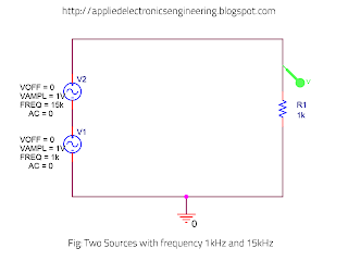 |
| Fig1: Signal Source with two frequencies(1kHz and 15kHz) |
The output signal waveform which contains the two frequencies is shown below-
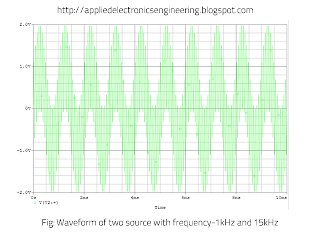 |
| Fig2: Waveform of signal with two frequencies(1kHz and 15kHz) |
The corresponding waveform spectrum is shown below. Notice that both frequency components have equal magnitude.
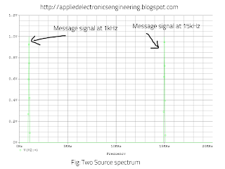 |
| Fig3: Spectrum of two frequency signal at 1kHz and 15kHz |
Now, lets add a pre-emphasis circuit which is an RC HPF to the above circuit above as shown-
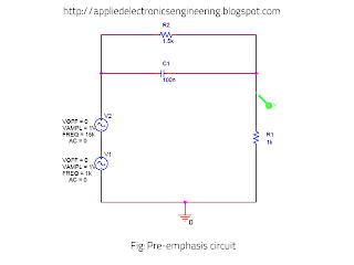 |
| Fig4: Pre-emphasis circuit |
The waveform of the signal at the output of the pre-emphasis is shown below-
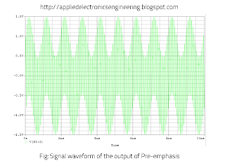 |
| Fig5: Waveform of output signal of pre-emphasis |
Now the spectrum of this signal is shown below:
 |
| Fig6: Spectrum of the output of pre-emphasis |
Now comparing the output signal spectrum of Fig 3 and Fig 6 we can see that the magnitude of the input signal at 15kHz is retained or equivalently emphasized while the magnitude of frequency component at 1kHz is decreased. This shows clearly that the RC HPF performs the pre-emphasis of the input signal.
De-emphasis:Now at the receiver RC LPF is used to de-emphasis the high frequency component and thus restore the original signal. The circuit for the de-emphasis is shown below:
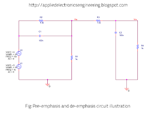 |
| Fig7: Pre-emphasis and De-emphasis Circuit |
The signal waveform of the transmitted and received signal is shown below-
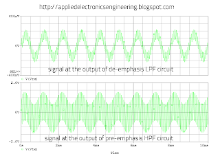 |
| Fig8: Signal waveform at the output of pre-emphasis and de-emphasis |
The output spectrum of the pre-emphasis and the output spectrum of the de-emphasis circuit is shown below-
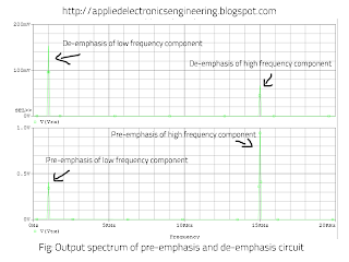 |
| Fig9: Ouput spectrum of pre-emphasis and de-emphasis circuit |
The Fig9 clearly shows that the pre-emphasis circuit does emphasis the high frequency component and that the de-emphasis circuit restore the high frequency component of the input message signal.


Tidak ada komentar:
Posting Komentar