In last altium designer tutorial it was shown how to
design an amplifer and how to bias the transistor using voltage divider biasing technique.
In this tutorial a
Bode plot graph in altium designer software for the previously designed CE amplifier is illustrated. Bode plot basically gives the frequency response of the transfer function or gain of the amplifier. Frequency response means how the magnitude and phase of the voltage gain varies with frequency. Overall, when a signal passes through an amplifier, the signal is amplified and phase shifted and this information is given by the magnitude bode plot and the phase bode plot.
Draw the schematic as shown below-
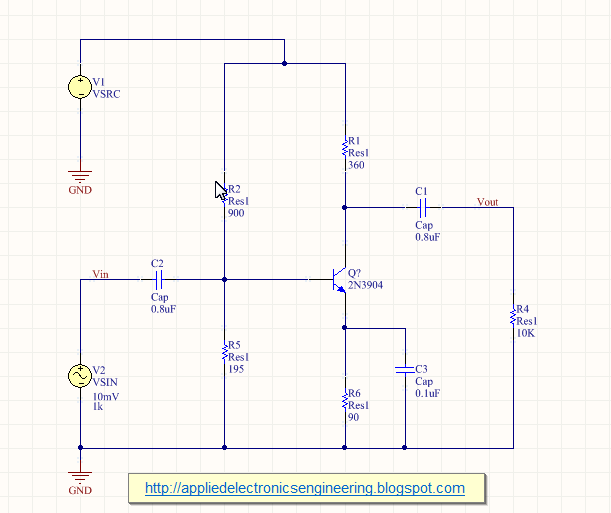 |
| Fig: CE Amplifier |
Now to get the frequency response of the voltage gain Av=Vout/Vin we first have to set up the simulation analysis. To do this either click on the Setup Mixed Signal Simulation icon on the toolbar or goto Design> Stimulate> Mixed Sim. Doing this will bring up the setup menu where you can select the desired simulation required. In our case we want to Bode plot which requires selecting the AC Small Signal Analysis. Select this as shown in figure below-
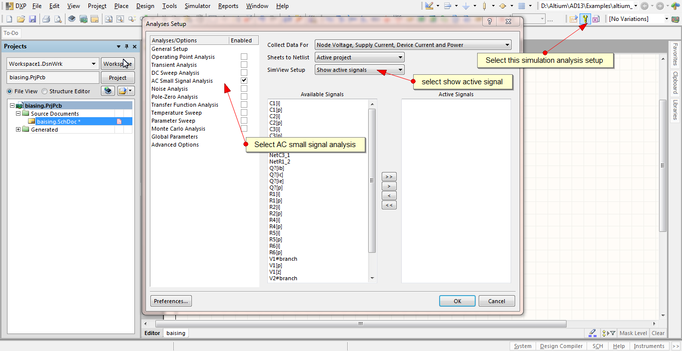 |
| Fig: Simulation Setting for Bode plot |
In the AC analysis tab, select frequency range from 1Hz to 1THz(it's high but its required to get the magnitude plot for our design) and select Decade as the Sweep type as shown in figure below-
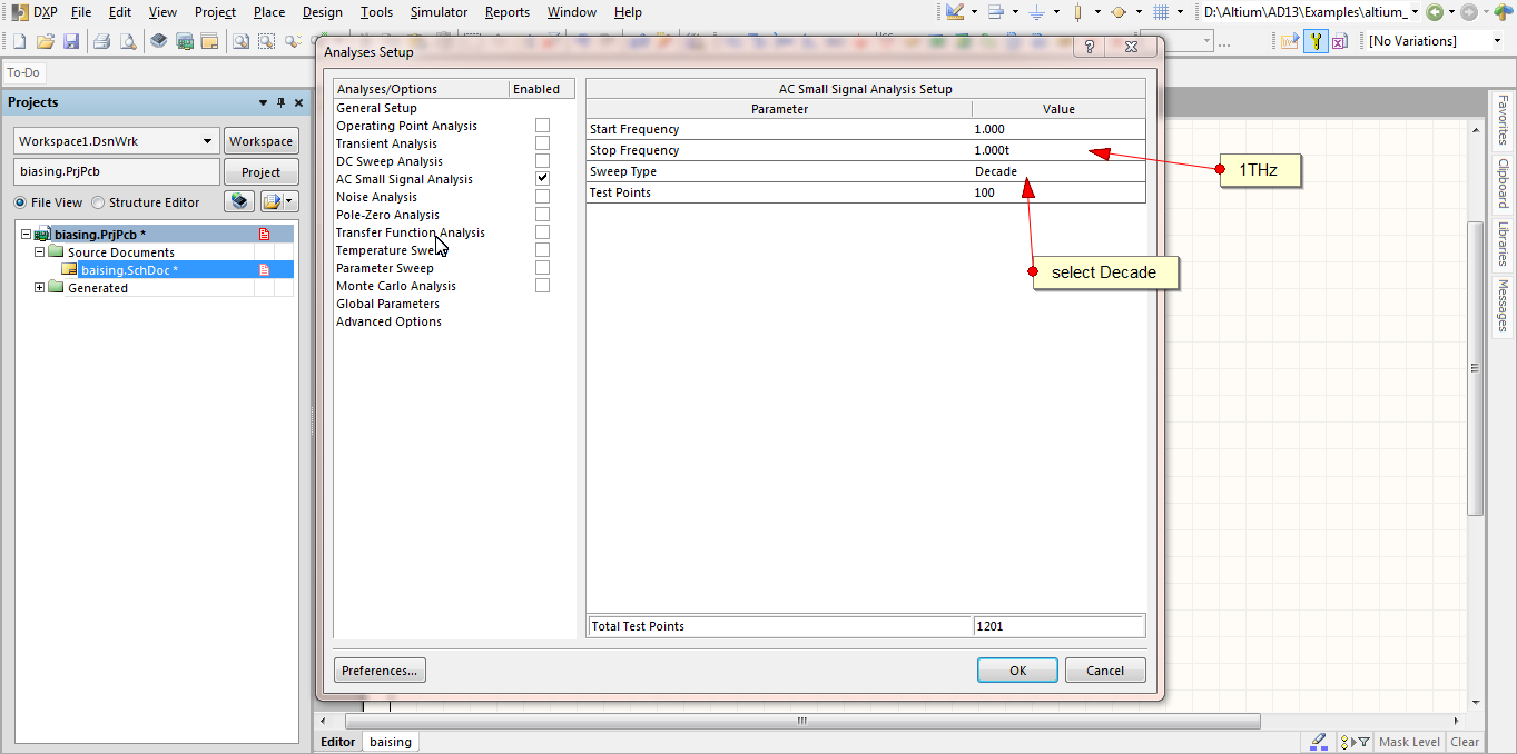 |
| Fig: Simulation Setting for Bode plot |
Once this is done run the simulation by clicking on the Run Mixed Signal Simulation button in the toolbar.
Because we have not yet specified which signal to trace altium designer shows some signal, here in this case it is showing the netc1_1 signal as shown-
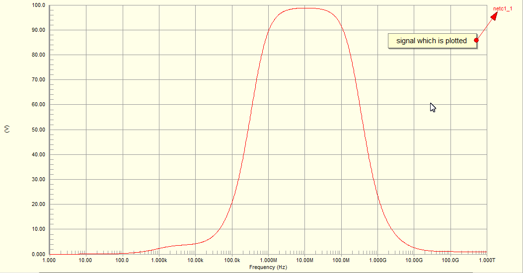 |
| Fig: Editing Signal |
Right click (or double click) on the signal and select edit wave.Then in the edit waveform window enter vout/vin and select magnitude(db) from the complex function option. Give some meaning full name to the signal such as voltage gain and click on create as shown below-
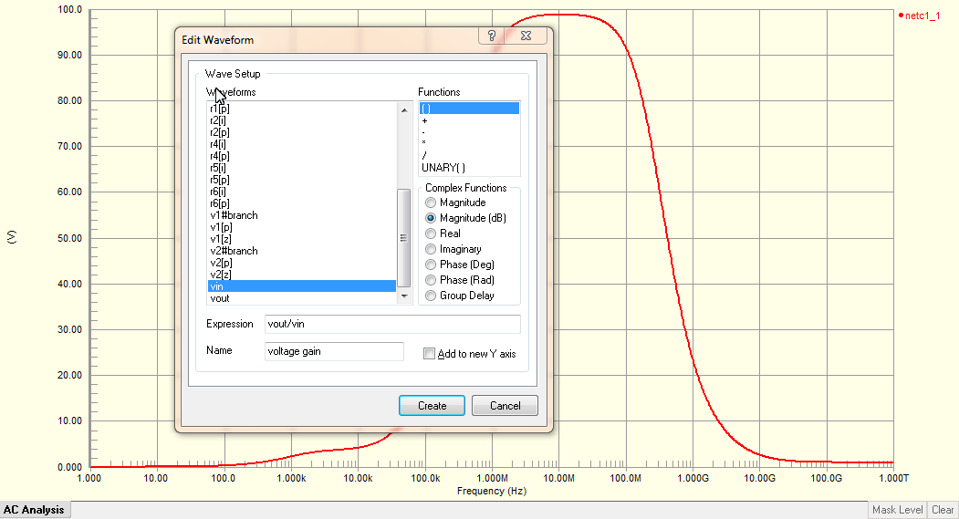 |
| Fig: Magnitude Bode plot |
The voltage gain magnitude in db is shown below-
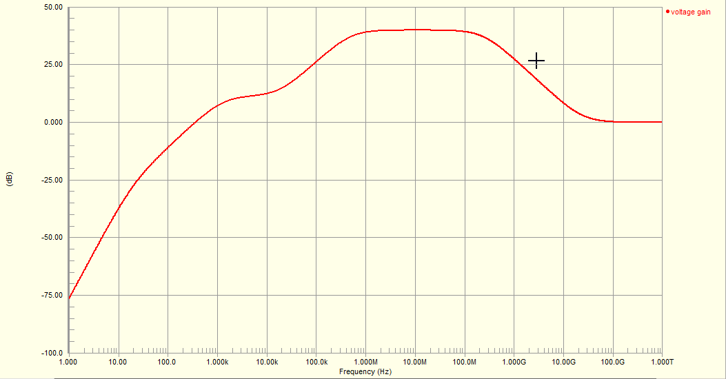 |
| Fig: Magnitude Response of Amplifier |
We need to figure out the lower and higher cutoff frequencies where the magnitude fall down to 3dB(-3dB) from the mid value of the magnitude. We can do this using marker. To use marker in altium designer waveform window, right click on the signal voltage gain and then select Cursor A as shown below-
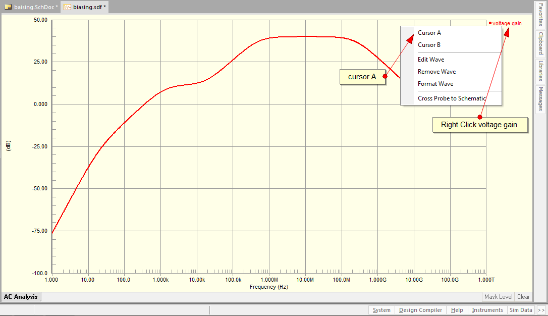 |
| Fig: editing -3dB magnitude response |
Drag the cursor a to somewhere in the middle of the top of the waveform where it has maximum value. This is illustrated below-
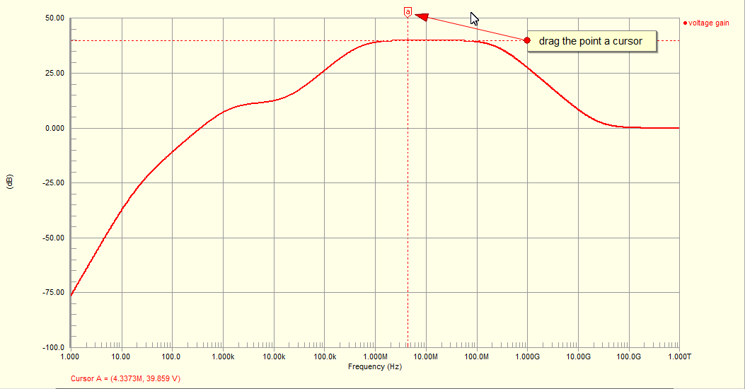 |
| Fig: editing -3dB magnitude response |
With respect to this point we will find another point where it decreases by -3dB. For this we require another marker, so as before, right click on the signal voltage gain and select Cursor B. To view the location of the -3dB point, drag the cursor b such that the difference B-A under the measurement in Sim Data window shows -3. Sim Data is docked usually at the right bottom of the screen. To get exact value you can zoom in by dragging a square into the point of place where you want to zoom in. This process is illustrated below-
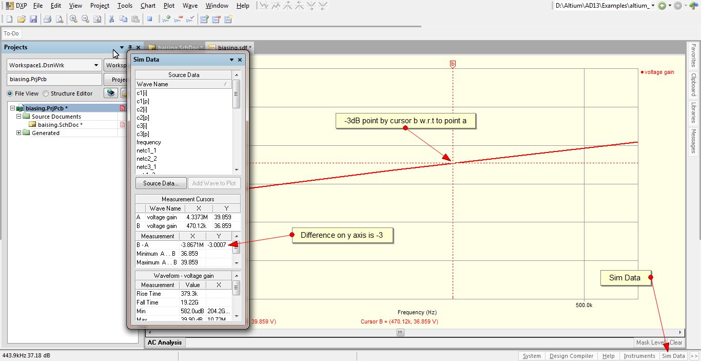 |
| Fig: editing -3dB magnitude response |
According to this amplifier design the lower -3dB cutoff frequency is located at a frequency of 417.12 KHz.
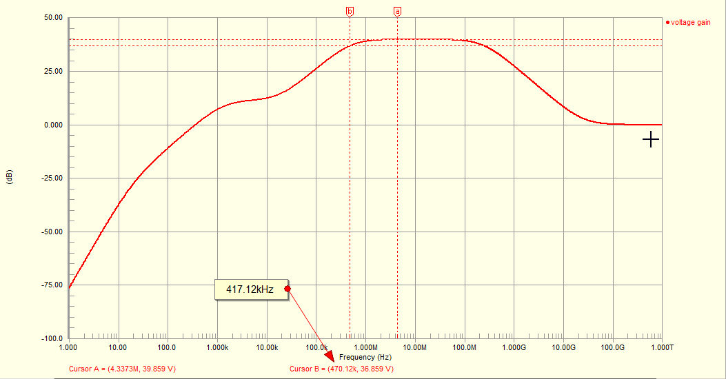 |
| Fig: -3dB location |
Similarly by dragging the same b cursor we can get the higher cutoff frequency as 247.63 MHz.
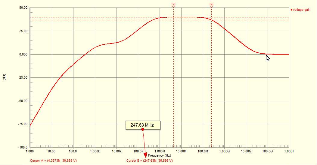 |
| Fig: upper cutoff frequency -3dB location |
To get the phase Bode plot, right click on the graph and select add plot. A wizard pops up. Give a suitable name such as phase plot. Click next until Add waveforms to the new plot is appears. Click Add and enter the expression for the voltage gain(vout/vin), give suitable name such as phase, and also select the Phase(Deg) under the Complex Function option. And then click Create and then Next to finish up the wizard. This process is shown below-
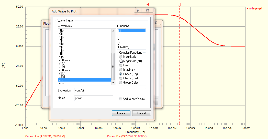 |
| Fig: Phase plot setting |
The new phase plot window appears as shown-
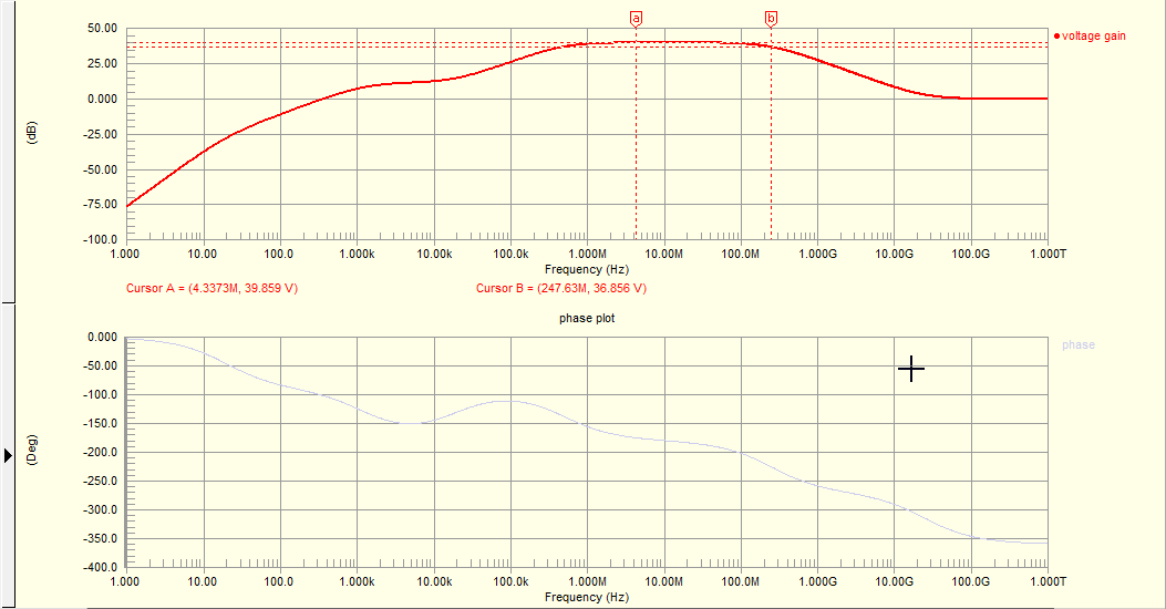 |
| Fig: Bode Plots |
Thus this two graph shows the frequency response or
Bode plot of the amplifier which was designed in the previous blog post.


Tidak ada komentar:
Posting Komentar