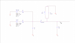
The schematic below shows a simple AM modulation realization circuit
In the schematic above, we apply message signal and a carrier signal to a diode and the output is passed through a tuned LC circuit. The message signal has frequency of 1k and the carrier signal has a frequency of 1MHz. The signal are mixed and fed into the diode(D1N4148) which performs the non-linear modulation. The output is a rectified version of the input signal. This is then mixed with the LC tuned circuit which is resonant also at 1MHz i.e. the carrier signal frequency. At the output we get a Amplitude Modulated signal.
The frequency of oscillation of the tuned circuit is given by-
\[f=\frac{1}{2\pi\sqrt{LC}}\]
with f = 1MHz and taking L = 10 microH we obtain the value of capacitance as C = 2.53nF
The output AM waveform is shown below-
Also see direct FM generation using varactor diode
 |
| Fig: AM Modulation schematic |
The frequency of oscillation of the tuned circuit is given by-
\[f=\frac{1}{2\pi\sqrt{LC}}\]
with f = 1MHz and taking L = 10 microH we obtain the value of capacitance as C = 2.53nF
The output AM waveform is shown below-
 |
| Fig: AM modulated signal waveform |
Tidak ada komentar:
Posting Komentar