Senin, 23 April 2012

Microelectronics Circuit Design and Analysis FREE Download

Download Free- Microelectronics Circuit Design and Analysis here at the link provided below. It contains topics like semiconductor, diodes, amplifiers, differential amplifiers, feedback amplifiers, power amplifiers, oscillators, digital microelectronics and IC designs. This book is useful with altium designer software which is used to design pcb board design from schematics diagrams. Also Altium Designer 10 (or Altium Designer 2013) supports co-design with FPGA which can be designed with Xilinx ISE. This book contains numerous example and solved exercises to help understand each component design.

Download Free- Microelectronics Circuit Design and Analysis
 Download Link:

http://filepost.com/files/8265cfa4/Muhammad_H._Rashid_Microelectronic_Circuits_Analysis_&_Design_2nd_Edition____2011.pdf


David Pozar Microwave Engineering Solution Manual

Download Solution Manual of Microwave Engineering by David Pozar
Solution Manual of Microwave Engineering
Download Solution Manual of Microwave Engineering by David Pozar for free from the link below. David Pozar's book Microwave Engineering is a book on design of microwave communication system and it explains the fundamental requirements for the design of amplifiers, filters, mixers and oscillators, S-parameters etc. Download Agilent ADS genesys for S-parameter simulation and system design, download CST Studio 2012 for antenna design, download cadence orcad for PCB layout design and schematic design, download MATLAB free for mathematical analysis and download comsol multiphysics to understand the underlying concept with this solution manual pdf of David Pozar Microwave Engineering ebook.


Download Link:

http://filepost.com/files/134m13c4/_Microwave_Engineering__2004.pdf/
Ringkasan ini tidak tersedia. Harap klik di sini untuk melihat postingan.

Practical Matlab Application for Engineers- Free ebook

Pratical Matlab Application for Engineers- Free ebookThis free matlab tutorial ebook "Pratical Matlab Application for Engineers" contains time domain and frequency domain matlab tutorials, AC and DC signal examples, Fourier and Laplace tutorial, DTFT,DFT, ZT and FFT matlab programming examples and also analog filter and digital filter examples in matlab software. If you don't have matlab software then you can download matlab software here in this blog.

Download Link:

http://www.filefactory.com/file/n977r1rfve5/n/Kalechman_M._Practical_Matlab_Applications_for_Engineers_CRC_Press_2008_en_708s_.pdf

Sabtu, 21 April 2012

Abaqus v6.10 Software Free Download

Abaqus v 6.10.1 ISO-TBE can be download here for free, the link is provided below. Stimulia Abaqus software supports multiphysics simulation helpful for mechanical, electrical, thermal, moisture simulation  and perform, analyze different materials like metal, plastic, rubber and others required for modelling and prototyping electronics consumer products. FEA Abaqus is based on finite element analysis modelling (fea modelling)which is very helpful in todays rapidly growing electronics industry for faster productivity and manufacture-ability of electronics system design end products while lowering the cost and design cycle.
Abaqus v6.10 Software Free Download
Fig: Abaqus v6.10 Software Free Download

Download links:

Simulia.Abaqus.v6.10.1.ISO-TBE.part1.rar [1.91 GB]
http://d01.megashares.com/?d01=4OTs5JD

Simulia.Abaqus.v6.10.1.ISO-TBE.part2.rar [1.04 GB]
http://d01.megashares.com/?d01=jtP4TvB


Other popular Free Electronics design software:

Xilinx ISE Design Suite 14.3 Free Download
Portable Matlab R2012 Free Download
Mentor Graphics Expedition Enterprise Free Download
Cadsoft Eagle Professional Free Download 
 

Free Download MPLAB IDE v8.10

Ringkasan ini tidak tersedia. Harap klik di sini untuk melihat postingan.

Download Atmel Studio 6 for Free

Download Atmel Studio 6 for Free
Download Atmel Studio 6 for free here. Atmel Studio is useful for avr programmer for development and debugging of Atmel ARM Cortex-M and Atmel AVR microcontroller. With this microprocessor based application you can learn and build, write machine code in C++, assembly language and for development of firmware.

Atmel Studio is useful for microcontroller and microprocessor designers. It is similar to Mplab IDE software from microchip. See download Mplab IDE for more information.

Download link for Atmel Studio 6 for free:

http://rapidgator.net/file/a932addebac9cfcc31072cabff614b0b/AtmelGallery.part1.rar.html
http://rapidgator.net/file/ce3cd5e3cb3601995447a80f2b8a4be1/AtmelGallery.part2.rar.html
http://rapidgator.net/file/c1c0401d64e3bde10f67415cb175524c/AtmelGallery.part3.rar.html

Dowload ipad excel spreadsheet apps for free

Dowload ipad excel spreadsheet apps for free
Fig: Ipad excel spreadsheet apps for free
Download Apple's ipad number v1.4 application for free from the link provided below. ipad (or iphone) number application is a spreadsheet application which can also be downloaded from apple from the app store. Here you can download for free. This ipad application is a spreadsheet application for apple's ipad,iPhone,ipod touch which can be used to create tables, charts, photos etc with just touch of finger. It can also be used for iphone spreadsheet or ipod touch excel spreadsheet application.

Download Link for IPAD EXCEL SPREADSHEET:

http://d01.megashares.com/dl/FK9QMA6/Apple.Numbers.v1.4.iPad.iPhone.iPod.Touch.NON.STOLEN-Lz0PDA.rar

Rabu, 18 April 2012

Download Comsol Multiphysics Simulation Software Free

download comsol physics for electronics design
Fig: Comsol Multiphysics for thermal analysis of IC on PCB
Comsol Multiphysics 4.3 is a simulation software based on electromagnetic simulation used for scientific research by engineers, scientist for electronic packaging design prototyping and viewing the designed product before manufacturing. The multiphysics environment allows product designers, engineers and researchers to create 3D model, design board, pcb prototype and view the electronics/ electrical parts, mechanical parts, chemical and fluids and it also provides interfacing and import/ export to other CAD and EDA software. Comsol simulation software is an EDA based on finite element method. Free download Comsol multiphysics links are given below

In particular the RF cosmol simulation software is useful to electronics designers to create 3D electronics components and evaluate performance and visualize the effect of RF heating, stress and elastic deformations.


Download links:

http://rapidgator.net/file/01d3f6cc50cbbde80c313933a92b3e25/COMSOL.Multiphysics.v4.3a.Multiplatform.ISO-TBE.part1.rar.html
http://rapidgator.net/file/6858ad59e71f03f943dc389dd8dae747/COMSOL.Multiphysics.v4.3a.Multiplatform.ISO-TBE.part2.rar.html
http://rapidgator.net/file/367a7f1a8a1f3d14777e6b0d05e11f2c/COMSOL.Multiphysics.v4.3a.Multiplatform.ISO-TBE.part3.rar.html
http://rapidgator.net/file/e66d816b186ae1a3a769355ca4bfc99f/COMSOL.Multiphysics.v4.3a.Multiplatform.ISO-TBE.part4.rar.html
http://rapidgator.net/file/030061a564264a9ebfcb64ed1d79f8fb/COMSOL.Multiphysics.v4.3a.Multiplatform.ISO-TBE.part5.rar.html
http://rapidgator.net/file/5af27abb7a0b46363b4f5c1a95036c79/COMSOL.Multiphysics.v4.3a.Multiplatform.ISO-TBE.part6.rar.html

or

http://extabit.com/file/29g2wym0iuxkk/COMSOL.Multiphysics.v4.3a.Multiplatform.ISO-TBE.part1.rar
http://extabit.com/file/29g2wym0iuxhg/COMSOL.Multiphysics.v4.3a.Multiplatform.ISO-TBE.part2.rar
http://extabit.com/file/29g2wym0iuxl0/COMSOL.Multiphysics.v4.3a.Multiplatform.ISO-TBE.part3.rar
http://extabit.com/file/29g2wym0iuo1w/COMSOL.Multiphysics.v4.3a.Multiplatform.ISO-TBE.part4.rar
http://extabit.com/file/29g2wym0iuo3o/COMSOL.Multiphysics.v4.3a.Multiplatform.ISO-TBE.part5.rar
http://extabit.com/file/29g2wym0iur84/COMSOL.Multiphysics.v4.3a.Multiplatform.ISO-TBE.part6.rar

or,

http://lumfile.com/itm5j4y9n3u0/COMSOL.Multiphysics.v4.3a.Multiplatform.ISO-TBE.part1.rar.html
http://lumfile.com/ie5jtld1ehi6/COMSOL.Multiphysics.v4.3a.Multiplatform.ISO-TBE.part2.rar.html
http://lumfile.com/5h8f8k6b1sb9/COMSOL.Multiphysics.v4.3a.Multiplatform.ISO-TBE.part3.rar.html
http://lumfile.com/0564q6s5oxhv/COMSOL.Multiphysics.v4.3a.Multiplatform.ISO-TBE.part4.rar.html
http://lumfile.com/gqlfh2ceuiln/COMSOL.Multiphysics.v4.3a.Multiplatform.ISO-TBE.part5.rar.html
http://lumfile.com/fd6uticpmbf1/COMSOL.Multiphysics.v4.3a.Multiplatform.ISO-TBE.part6.rar.html

download Microsoft Visio 2013 for free

Download ms visio 2013 free
Download the latest version of microsoft visio 2013 for free. Microsoft Visio 2013 is a project management software is useful for project management works and used by project managers, ceo, engineers and the like.

Microsoft Visio 2013 lets you create diagram of complex project, schedule task, assign resources to task, write work description etc. Electronic engineer can use this software to plans for design projects, from starting electronics circuit design, electronics circuit simulation, pcb design, electronic packaging design and pcb manufacturing. This Microsoft Visio 2013 download free is also useful for anybody in their project and to student for academic work.
 
Activate Method (Phone Method is the best)(Update April 13, 2013):

http://pastebin.com/vEn1abuC
VL Version must use KMS Tool to activate. This key only for Retail version


USE Advance Token Manager to BACK UP Your LICENSE 
 http://disk.karelia.pro/fast/f7v2LmF/

Download Links for:
Microsoft Visio/Project Professional 2013 Retail + VL (x86/x64)
Incl. Keys/KMS Tools

For Visio Professional 2013 VL (x86) - (English) 
  
https://safelinking.net/p/6578e78463
or,
https://safelinking.net/p/1c5c9d46dd
or,
https://safelinking.net/p/90817b2708
https://safelinking.net/p/7f61c87861
https://safelinking.net/p/3a3666b1c0
https://safelinking.net/p/8edab061a4

or,
https://safelinking.net/p/f20d177e96
https://safelinking.net/p/a421820c41
https://safelinking.net/p/3f67d53f0c
https://safelinking.net/p/8699edc7d3


For Visio Professional 2013 VL (x64) - (English)

 https://safelinking.net/p/b8c1867b9b
or,
 https://safelinking.net/p/7c395e5bae
or,
 https://safelinking.net/p/7893d18cb4
https://safelinking.net/p/d2fde95781
https://safelinking.net/p/7c18cb1fe2
https://safelinking.net/p/6f385f3323

or,
https://safelinking.net/p/9628e28ae7
https://safelinking.net/p/f97984af71
https://safelinking.net/p/dffa8703af
https://safelinking.net/p/68cd51cf02


For Project Professional 2013 VL (x86) - (English)

https://safelinking.net/p/e4c8a015f0
or,
https://safelinking.net/p/0a02ff2402

 or,
https://safelinking.net/p/d486e1b895
https://safelinking.net/p/ffc0b408df
https://safelinking.net/p/7e483bdd13
https://safelinking.net/p/de3a75e655

or,
https://safelinking.net/p/e4c8bd649c
https://safelinking.net/p/653d8c8c0f
https://safelinking.net/p/6489e6b721
https://safelinking.net/p/405e478c2d


For Project Professional 2013 VL (x64) - (English)
  
https://safelinking.net/p/72968a8d2a
or
https://safelinking.net/p/5628373544
or,
https://safelinking.net/p/ceff0bb6a0
https://safelinking.net/p/d0dbe2f9be
https://safelinking.net/p/efaee46ef9
https://safelinking.net/p/a9a5caed74

or,
https://safelinking.net/p/b42ac64e74
https://safelinking.net/p/14308f40c0
https://safelinking.net/p/80fb35d41c
https://safelinking.net/p/0344938561 


Also,

Visio Professional 2013 (x86) – (English)
File Name: en_visio_professional_2013_x86_1123796.exe
Languages: English
SHA1: cc91588734c11afa15703e29169919fd476e4e60

https://safelinking.net/p/6cce505b22

or,
https://safelinking.net/p/7829895b70
And,

Visio Professional 2013 (x64) – (English)
File Name: en_visio_professional_2013_x64_1123802.exe
Languages: English
SHA1: 6812cb3a4967824fefe29e302968f13b98fa85c6 
https://safelinking.net/p/be673359cb
or,
https://safelinking.net/p/78648a9f01
Similarly,

Project Professional 2013 (x64) – (English)
File Name: en_project_professional_2013_x64_1123813.exe
Languages: English
SHA1: ed737bd07ec815d898f5a72b773f529a8d3aafdc 
https://safelinking.net/p/4d182a4aa9
or,
https://safelinking.net/p/a6b383ae27
And,

Project Professional 2013 (x86) - (English)
File Name: en_project_professional_2013_x86_1123807.exe
Languages: English
SHA1: 3a44d77f437fac9f59a9afe5d1915a81106b0fa4 
https://safelinking.net/p/8a59ac9c41
or,
https://safelinking.net/p/0258734c8c

Selasa, 17 April 2012

Free Download Autodesk for Electronics Product Development

Download AUTODESK SIMULATION DFM V2014 WIN64-ISO for free. Autodesk is a 3D product design software that can be used to prototype electronics product. After having designed the electronics circuit, pcb board for manufacturing, the pcb board can be further imported in the autodesk software to design the 3D housing and get a visualization of the final product before it is sent to the product development firm. Autodesk simulation software for electronics is useful for those who provides or is interested in providing 3D electronics product development services or consumer electronics product development. The free download Autodesk 3D product design software is 1.05GB in size.

autodesk free download

 Download Link:

http://uploaded.net/file/1qtf1k99/AUTODESK.SIMULATION.DFM.V2014.WIN64-ISO.rar

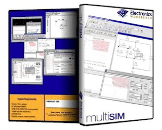
Download NI Multisim Ultiboard PowerPro 12.0.1 Free

Download Multisim & Ultiboard (Circuit Design Suite) PowerPro 12.0.1 for free. Multisim is used to create schematics of circuit board and Ultiboard is used to design and prototype printed circuit board. This PCB manufacturing software is developed by Analog Devices National Instrument Corporation.

NI Multisim Ultiboard PowerPro 12.0.1Analog Devices Multisim allows electronics engineers to create and enter schematics of electronics product, perform simulation, evaluate performance. During the design of circuit board schematics electronics components have to be added which can be easily done from the database. If there is no parts available then new part can be created. The parts footprints search can also be performed and associated with the part. In Multisim the different color of the components in the schematics shows which component has available simulation model and footprint and which components has only simulation property. Once the ERC checks, simulation analysis is performed the schematics to pcb layout transfer can be done.

Analog Devices Ultiboard is a EDA tool to prototype PCB board. The circuit board schematics from the Multiboard is transferred to Ultiboard to prototype printed circuit board. The transfer of schematics from Multiboard to Ultiboard is easy with simple few step clicks. Once the transfer is complete the Ultiboard software is used for pcb production process that involves creating board outline, the mechanical holes, annotation, manual and auto-routing, layer assignment, power and ground plane assignment etc. Once the PCB board design is completed the Gerber PCB file, DFX files for pcb production can be generated and sent to the pcb manufacturer.

Multisim 12 full version free download links:

http://rapidgator.net/file/44132626/Multisim_12.0.1.rar.html
or,
http://lumfile.com/6753s471mhbb
or,
http://extabit.com/file/279fqtda2o0je

Free Download Labview 2012

Download Labview NI
Fig: NI Labview
Download Labview 2012 for free. Labview is a EDA tool to solve engineering problems using automatic data collection and testing. This software can be used with Multisim Ultiboard software for solving electronics design problems.

Labview 2012 from National instrument is a graphical programming tool used by researchers, scientists and engineers around the globe. It is a graphical system design tool that can be used for example to design pulse code modulation system, digital modulation, encoders decoders, multiplexers with the use of VI modules. There are library of VI modules for example for flip flops, multiplexers, registers, FPGA devices, micro-controllers. It can also be used for programming embedded system and FPGA then the designed system can be implemented in Xilinx ISE design suite. The designed system can be converted into program and exported to other EDA. It ease the presentation and processing of data.

Labview download student can be to generate and save realistic waveform data obtained from simulating the circuit schematics created from Multisim. Once the output data is collected the circuit schematics to PCB layout is performed, that is the schematics from the Multisim is transferred to Ultiboard PCB prototyping software. After the PCB is produced from the Gerber PCB file the physical PCB board with components on them can be again tested with the Labview to compare the results.

Free Download Link for Labview 2012 :

http://uploaded.net/file/7kwwdyee/Labvi1ps.part01.rar
http://uploaded.net/file/l44p8g7p/Labvi1ps.part02.rar
http://uploaded.net/file/qtdn9qnq/Labvi1ps.part03.rar
http://uploaded.net/file/7bolsjrt/Labvi1ps.part04.rar
http://uploaded.net/file/hdzzwuzz/Labvi1ps.part05.rar
http://uploaded.net/file/n1jdq94r/Labvi1ps.part06.rar
http://uploaded.net/file/pwqid7rn/Labvi1ps.part07.rar
http://uploaded.net/file/mrt34nlr/Labvi1ps.part08.rar
http://uploaded.net/file/tnj5515s/Labvi1ps.part09.rar
http://uploaded.net/file/uotq63vn/Labvi1ps.part10.rar
http://uploaded.net/file/1cxnp8zm/Labvi1ps.part11.rar

Senin, 16 April 2012

How to design pcb in orcad?

Orcad cadence is a popular pcb design software used by professional engineers around the globe. Here how one can learn to design pcb using orcad pcb software quickly is described. First of all you have to download cadence orcad pcb software.

The major general steps to designing a pcb with orcad are:
  1. Start orcad capture and draw the schematics
  2. Perform Simulation and verify result and replace/add components according to your result requirements
  3. Find and assign the footprints(names) for all the schematics symbols
  4. Perform annotation
  5. Perform DRC
  6. Create Netlist
  7. Open orcad PCB Editor
  8.  Define board outline
  9. Place the mechanical components
  10. Place the electrical components
  11. Create layers if multiple layers are required
  12. Place copper pours(multiple layers)
  13. Check electrical rules, physical rules and spacing rules in the constraint manager
  14. Perform manual and automatic routing
  15. Generate Artwork for manufacturing

Once you have downloaded the orcad software, you have to start the orcad schematic capture which is a tool where you can enter the schematics or circuit diagram of the electronics system which you want to design. This requires you to place parts from libraries. There are two kinds of libraries, one that has footprints, part symbol with simulation information and those with only part symbol but without simulation information and/or footprints. Any part used in electronic system design prototyping need its schematic symbol for identification, simulation profile(how it works) and footprints(for pcb generation). If there is no part symbol(and/or simulation profile) then you have to create a new one which you can do so either from orcad capture window or from the model editor application.

Once the schematics of the electronic system to be designed is complete. The next step is to perform simulation. Once the simulation is verified the schematics parts are assigned their footprints. If there is no footprint available then you have to either search for footprint or create a new one using pad designer or using the new part option in the orcad PCB designer.Then the next step is annotation(giving unique identification names to parts) and perfrom DRC(Design Rule Check) to check any error. If there is no DRC then you can create a netlist of your circuit.

This netlist is required by the PCB designing software. During the netlist creation you have the option to automatically open the Orcad PCB editor(or you can independently open the PCB editor and go to open menu to open the netlist file). Once the PCB editor is open you have to create a board outline and start placing components both mechanical components that will hold the pcb board and the electrical components(capacitor, resistors, amplifiers etc).

If it is required to have more than two layers then multiple layers has to defined next. After this pouring of copper planes and construction of vias and the fanout has be carried out. Then the spacing between the copper traces, length width of the copper traces and other electrical and non electrical constraints have to be defined prior to routing the traces using the constraint manager. Once the constraints are defined the next step is to perform routing. The routing can be performed manually for critical nets(for eg power and ground nets) and fixing such nets and then the auto-routing to non-critical nets can be applied for speed-up. The last step is to generate artwork which contains all the information of the pcb to be manufactured, this file(extension usually gerber) is sent to the pcb board manufacturer.

To learn to design pcb in orcad, we recommend you to Download Kraig Mitzner Complete PCB Design Using OrCad Capture and Layout 2007, which you can do so for free

Download Fundamental of Microelectronics Behzad Razavi

Download link for Fundamental of Microelectronics by Behzad Razavi is provided here below.
download razavi microelectronics pdf

Fundamental of Microelectronics by Behzad Razavi is a popular book in the electronics industry and among scholars. This preview book contains description on easy to understand topics on rf electronic and microelectronics components. Fundamental of Microelectronics by Behzad Razavi also gives readers the concept of microelectronics and the difference between electronics and microelectronics. Fundamental of Microelectronics by Prof. Behzad Razavi contains lots of solved exercises of real practical on field problems and their solutions. This is a book that electronics engineers should have.


Download link for Fundamental of Microelectronics by Behzad Razavi in pdf form

http://filepost.com/files/d5c2e9ed/Behzad_Razavi_Fundamentals_of_Microelectronics__2006(1).pdf
or,
http://fp.io/d5c2e9ed/

Other free useful electronics design ebooks :

Agilent Genesys 2012 Free Download

Agilent Genesys 2012 Free Download
Fig: Agilent Genesys 2012 Free Download
Download Agilent Genesys - an RF and Microwave electronics board design software that is used widely by RF circuit board design engineers and PCB Board Designers.

As an overview example on application of this electronics board design software - it can be used for drawing schematics diagram of an electronics circuit. Then the designed electronics circuit can be analyzed such as performing S11 and S21 S-parameter analysis, smith chart analysis. Another great feature of this pcb board design software is that the values of the circuit components can be varied easily and simultaneously check the output graph to optimize the electronic component value for desired output. This work is much easier to do in agilent genesys than for example in cadence orcad software. Also in agilent genesys electronics board design software circuit schematics of any transmitter or receiver can be designed easily and then the spectrum of signal at any node in the designed circuit can be viewed by simply clicking on the desired node and clicking on the spectrum option that pops out. The best part of genesys is that the once the transmitter or receiver is designed the power level link budget can be viewed on a graph. This means that the gain and attenuation power level in dB at input and output of each components such as mixer, amplifiers, filters can be viewed. This gives many information of the system performance. For example it can be used to see which component is causing unexpected power loss and which component can be modified to obtain desired better output power level. Moreover, the input power in dB can be varied with easy scroll part and the power link budget in the circuit will be changed automatically.

Other advantages of using this electronics board design software is the automatic optimization of components values, automatic generation of strip lines and pcb layout. Then using this pcb board design software the pcb layout can then be optimized further with agilent momentum electromagnetic tool at desired frequencies. The optimized circuit can then be transferred to the PCB layout tool to generate the Geber PCB files for manufacturing. Agilent Genesys pcb board design software also supports 3D view of the designed pcb board with the components on it so that engineers can visualize the final design.

Agilent Genesys 2012 electronics board design software free download links

http://rapidgator.net/file/24378299/AgilentGenesys.2012.01.part1.rar.html
http://rapidgator.net/file/24378297/AgilentGenesys.2012.01.part2.rar.html
http://rapidgator.net/file/24378301/AgilentGenesys.2012.01.part3.rar.html

Or,

 http://letitbit.net/download/71966.7173c716688574d4db907d4f16f0/AgilentGenesys.2012.01.part1.rar.html
http://letitbit.net/download/95061.9c00043acb7f1ff8f799c87eb90e/AgilentGenesys.2012.01.part2.rar.html
http://letitbit.net/download/62216.6b8944657124aee454ddc3ec1f2c/AgilentGenesys.2012.01.part3.rar.html


Other Similar EDA software for downloads:

Download Cadence Orcad 16.5 PCB Design Software

Cadence Orcad 16.5 Free Download
Fig: Cadence Orcad 16.5 Free Download
Cadence Orcad 16.5 is an integrated tool for schematic design entry, circuit board design, simulation and pcb layout board design software for designing electronics products. It is used by professional engineers and circuit board designer around the world for schematics drawing of electronics circuit board and for PCB board Prototyping.

The design step to design PCB board is to enter the electronics schematics, then to perform simulation and other analysis. If the simulation result are correct then footprint are added for PCB board design. Then the next step is to transfer the designed Orcad schematics to PCB layout tool called allegro PCB. The nice feature of this PCB board design software is that there are lots of automation during the transfer process of orcad schematic to PCB board design making it easy for designers to quickly develop PCB for manufacturing. During the PCB design, it provides very useful features such as components placing, auto routing and design of multiple layer pcb and others. After the PCB board design is completed, it generates Geber PCB file required by the PCB manufacturers. Gerber PCB is the final file required which in case of orcad is generated by the artwork tool. See the orcad capture video tutorials.

Download cadence orcad 16.5 along with hotfixes from the link provided below.

 Download Links:

Cadence SPB/OrCAD v16.5 - [2.15 GB]:
  • https://safelinking.net/p/d08a268f8d
Cadence SPB/OrCAD v16.5 Latest Hotfix - v16.5-S033 (2012-10-31) - [632 MB]:
  • https://safelinking.net/p/5bebcab126
Cadence SPB/OrCAD v16.5 Installation Instructions - [2.11 kB]:
  • https://safelinking.net/p/d0f8fb8058
Other PCB Design Software Download Links:
Cadence capture Schematic and Orcad PCB editor tutorial ebook in pdf format:

    Jumat, 13 April 2012

    Thomas H Lee - The Design of CMOS RF IC

    Ringkasan ini tidak tersedia. Harap klik di sini untuk melihat postingan.

    Diptrace Download for Free

    Download Diptrace for free. Diptrace is a PCB circuit board prototyping software used for producing electronics products. It is a widely accepted PCB Manufacturing Software used by electronics students, engineers, researchers and Electronics Design Companies.

    Diptrace PCB circuit board prototyping tool has schematic editors, pcb layout editors, simulation and analysis tools, error checking capabilities like ERC, DRC, manual and auto routing capabilities, generates bill of materials(BoM) reports, Gerber PCB files, NC drill files, DFX files and others.

    It has also easy to use interface, with library of components of different electronics manufacturers such as National Semicoductor, Analog Device, Philips etc. The part search is very easy to use and is at the top horizontal bar with names of the manufacturing companies. If there is no part available then the part can be created and imported into the Diptrace software. 

    Some of the difference between the Orcad capture PCB circuit board prototyping software and Diptrace are like the zoom in and out capability which is found in Diptrace but not in Orcad capture. Another difference is that when any wire is hovered with the mouse the wire becomes highlighted showing the wire connection to different part in the design. This is useful in a large project circuit board.Diptrace PCB manufacturing software is easy to start and learn. The Diptrace website has a excellent video tutorial to learn schematics, designing layout, auto routing and generating gerber pcb for PCB manufacturing
    Download link for DipTrace v2.0.07:

    Kamis, 12 April 2012

    Most Popular Electronics Design Software

    The most popular electronic system design software used by professional electronics and computer engineers are are follows:
    Most Popular EDA
    Most Popular EDA
    Cadence comes with combined tools from orcad, allegro and pspice. Their functions are combined in one EDA package called Cadence. For example, pspice is for modelling and simulation of electronics components and electronic software. Orcad and allegro is used for PCB layout design for PC Board manufacturing. Thus Cadence is an integrated tool that allows one to start the schematic design and finish up the project with PCB for manufacturing. The schematic is drawn with the tool called orcad capture.
    • Agilent ADS(Advanced Design System)
    Agilent ADS is another popular tool useful for communication system designer. It contains libraries and set-up for simulation of different communication system such as GSM, EDGE, Microwave Communication system, CDMA, 3G etc. It is more often used for microwave communication system design for s-parameter, power spectral density calculation, harmonic simulation etc. It can also be used for antenna designs, layout of PCB, microstrip simulation and once the design has been verified and agreed to the part can be transferred to the Cadence software.

    EDA Software Proteus is becoming increasingly popular electronics design software. It is used for microprocessor simulation with PCB design. It supports schematic drawings with its system component called ISIS schematic capture.  Other components of software Proteus is the Virtual System Modelling(VMS), ARES PCB layout for pcb design. Other features includes 3D simulation view, footprints library support etc. Download software proteus links for various version are provided in this blog.
    Mentor graphics expedition provides integration of PCB design flow to provide better productivity, mangement of components and faster manufacturing ability. Like other PCB design software, it provides schematic design ability, symbol and libraries, interconnectivity, constraint manager, BOM generation, PCB layout, component placement, simulation, thermal analysis, pcb packaging for manufacturing etc.
    Altium Designer is also a PCB layout designing software. It also supports FPGA and embedded system design. 

    CST Studio Suite 2012

    CST Studio Suite is contains antenna modelling software called  CST Microwave Studio, cable modelling software, particle modelling software, pcb modelling software, CST EM studio, CST MPhysics  and because of integrated solution to different problem domain it is called suite. CST microwave studio is popular to practicing electronics design engineers. It provides 3D visualization of electromagnetic waves around the designed system such as cell phones.

    Altera Edition ModelSim
    Xilinx ISE design Suite v14
    Mathworks Matlab: R2012a v7.14.0.739 Portable
     

    Rabu, 11 April 2012

    Download Mentor Graphics Expedition Enterprise Free

    Download Mentor Graphics Expedition Enterprise Free
    Download Mentor Graphics Expedition Enterprise Free
    Download Mentor Graphics Expedition Enterprise Free. Mentor Graphics Expedition Enterprise is an integrated PCB circuit board design, PCB layout board design, PCB manufacturing and simulation software.

    Mentor Graphics Expedition has all the PCB circuit board design features that is designed to reduce the PCB design cycle. For example, it allows concurrent working on the same PCB layout board design project, excellent PCB documentation management, supports PCB prototyping that reduces time for final PCB manufacturing.

    PCB manufacturing time is crucial in today's competitive world and many engineers believe that Mentor Graphics Expedition PCB manufacturing and development is reduced by 30 to 40%. As an example of application- it can be used to design RF communication system, perform thermal analysis, FPGA/ PCB co-design, integrated A/D & RF design, digital design and much more.

    This is useful for individual electronics engineers, PCB circuit board designers and/or for large electronics design companies.

    Download Link:

    http://shareflare.net/download/48402.45853d8808181ab8fd8978838297/MG_EE7.9.3.part1.rar.html
    http://shareflare.net/download/67546.64a9b6b86181823ad5e1fda386f6/MG_EE7.9.3.part2.rar.html
    http://shareflare.net/download/35738.399984e6cf0b606c7822210ed757/MG_EE7.9.3.part3.rar.html
    http://shareflare.net/download/04797.0925b2faa52d6e96ac910249a74e/MG_EE7.9.3.part4.rar.html
    http://shareflare.net/download/83440.8e831eedef983305951a7b68d882/MG_EE7.9.3.part5.rar.html
    http://shareflare.net/download/52884.5aa4a078f476d4680f62405ca1b1/MG_EE7.9.3.part6.rar.html
    or
    http://ul.to/xjkagjdx/MG_EE7.9.3.part3.rar
    http://ul.to/polcgu67/MG_EE7.9.3.part5.rar
    http://ul.to/eli49zcz/MG_EE7.9.3.part2.rar
    http://ul.to/23dx2a18/MG_EE7.9.3.part6.rar
    http://ul.to/vlznfcld/MG_EE7.9.3.part4.rar
    http://ul.to/dgibdf80/MG_EE7.9.3.part1.rar
     Or,
    http://turbobit.net/9axnlif0glcu/MG_EE7.9.3.part1.rar.html
    http://turbobit.net/mgf883frog7i/MG_EE7.9.3.part2.rar.html
    http://turbobit.net/dx1xowbo2bqi/MG_EE7.9.3.part3.rar.html
    http://turbobit.net/x4uetosv1vx2/MG_EE7.9.3.part4.rar.html
    http://turbobit.net/91k6arw7lseo/MG_EE7.9.3.part5.rar.html
    http://turbobit.net/35zlgsz9u39s/MG_EE7.9.3.part6.rar.html

      Download Altium Designer 10 Library & Documentation

      Download Altium designer 10 library for free. PCB libary Altium Designer 10 contains simulation models and footprint of electronics components from different vendors.

      Download Altium designer 10 library
      Picture: Download Altium designer 10 library
      Altium Designer 10 is a PCB circuit board design and simulation software. This Altium designer library and PCB documentation can be imported into Altium designer 10 and use the components desired. Without the Altium Designer library you have to create component and footprint from within the Altium Designer 10. Hence downloading this library will reduce the component model and footprint creation.

      This Altium designer 10 library is a database, a collection of component simulation model and footprints from major electronics manufacturing companies like the Samsung, Philips, Analog Inc, National Instrument, Digi International, Hitachi, Atmel, Altera, Agilent Technologies, Actel, Zilog, Xilinx and others.

      Download link for Altium Designer footprints libraries:

      http://ul.to/e0zy03fu
      http://ul.to/xxag2gw7
      http://ul.to/qv0cg9dg
      http://ul.to/zkxxvmmz
      http://ul.to/76utmvi3
      http://ul.to/7dykt3o8

      or

      http://ryushare.com/281bd4d7c296/deal10lido.part1.rar
      http://ryushare.com/29ed7e21e62a/deal10lido.part2.rar
      http://ryushare.com/27330032b43e/deal10lido.part3.rar
      http://ryushare.com/2904a97cd58a/deal10lido.part4.rar
      http://ryushare.com/29ed7e21e62e/deal10lido.part5.rar
      http://ryushare.com/281bd4d7c299/deal10lido.part6.rar

      OR,

       http://extabit.com/file/2dubsisdx5k56/deal10lido.part1.rar
       http://extabit.com/file/2dubsisdx5dtm/deal10lido.part3.rar
      http://extabit.com/file/2dubsisdx5dsq/deal10lido.part2.rar
      http://extabit.com/file/2dubsisdx5dxm/deal10lido.part4.rar
      http://extabit.com/file/2dubsisdx5gy2/deal10lido.part5.rar
      http://extabit.com/file/2dubsisdx5gyi/deal10lido.part6.rar

      BluePrint-PCB 3.0.0.571 with CAM350 FREE DOWNLOAD

      Download Blue-print PCB software for Free
      Download Blue-print PCB software for Free
      Download BluePrint PCB software for free. It is a PCB documentation software that ease the analysis, redesign PCB, PCB report generation work and shorten the PCB manufacturing process.

      PCB documentation is an important step in the PCB design cycle. It is required to record the PCB design for future reference, for review to senior engineers, to check the final design, for presentation for the clients before PCB manufacturing and for similar other reasons.

      BluePrint-PCB CAM350 from Downstream Technologies is such a PCB documentation tool that allows electronics PCB designers to import PCB design files and create PCB documentation. With this you can import PCB design files like the Gerber PCB, CSV, ODB++, NC drill, DFX files from PCB design software like Cadence Allegro, PADS, Zuken CADSTAR, Mentor Graphics Expedition, Altium Designer 13, Proteus software etc. After importing the design files, Blueprint PCB can be used to create a document that shows the details of the designed PCB assembly. PCB assembly details includes the holes sizes, the mechanical parts, pins, chips, the electronics parts, the BoM, the drill chart, the drill pattern etc. It can also import audio and video files to make the documentation more understandable. Once the documentation design is complete the PCB document can be exported in pdf format, microsoft format, html format and other format. These data can be for PCB manufacturing to the manufacturer.

      PCB documentation is one part of the PCB design cycle which can consume time if the project is large. In a large project the documentation becomes hazardous, important notes of the design can be easily lost. BluePrint PCB documentation software helps engineers to overcome these problems, help in systematic documentation and reduce the design cycle of PCB manufacturing.

      Download Links:

      http://www.wupload.com/file/172548312/BluePrint-PCB.v3.0.0.571.with.CAM350.v10.5.0.471-RECOiL.part1.rar
      http://www.wupload.com/file/172548315/BluePrint-PCB.v3.0.0.571.with.CAM350.v10.5.0.471-RECOiL.part2.rar
      http://www.wupload.com/file/172548325/BluePrint-PCB.v3.0.0.571.with.CAM350.v10.5.0.471-RECOiL.part3.rar
       or
       http://www.filesonic.com/file/1991793721/BluePrint-PCB.v3.0.0.571.with.CAM350.v10.5.0.471-RECOiL.part1.rar
      http://www.filesonic.com/file/1991793741/BluePrint-PCB.v3.0.0.571.with.CAM350.v10.5.0.471-RECOiL.part2.rar
      http://www.filesonic.com/file/1991793841/BluePrint-PCB.v3.0.0.571.with.CAM350.v10.5.0.471-RECOiL.part3.rar

      Selasa, 10 April 2012

      Analysis and Design of Analog Integrated Circuits

      Ringkasan ini tidak tersedia. Harap klik di sini untuk melihat postingan.

      Download CADsoft Eagle Professional 6.3 Free

      cadsoft eagle 16.3 download free
      eagle 6.3 download
      Download CADsoft Eagle professional free. CADSoft Eagle Professional is a popular PCB Prototyping software that can be used to create schematics, design and prototype printed circuit boards.

      Eagle PCB Prototyping software comes in free version as well as in bound version that is you have to buy this CADsoft Eagle professional software. The free PCB design tools from eagle is a simple PCB design software that does not have all the feature of this software. Some of the difference between the Eagle free PCB design tools and the professional version is the limitation of the board size, only 2 layer support and also there is no technical support. Thus the free version is just a simple PCB design software meant for beginners.

      Like other PCB Prototyping software, Eagle Professional provides all tools to prototype printed circuit boards. It has schematic design entry tools, library support, footprints, simulation and probes, schematics to PCB layout tools, 3D view of the PCB layout, DRC, BoM, generates standard Gerber PCB files, has auto routing tools and others. 

      Download link for Cadsoft Eagle PCB Prototyping Software are below:

      http://uploaded.net/file/atv2bt72/CADsEagle.Pro.6.3.0.rar
      http://letitbit.net/download/33623.352b21bbfbaf3e0bfeb9c7ac3666/CADsEagle.Pro.6.3.0.rar.html
      http://shareflare.net/download/34606.36f09ac9af0e981801ffad5bbe5c/CADsEagle.Pro.6.3.0.rar.html

      Senin, 09 April 2012

      Behzad Razavi RF Microelectronics ebook download free

      Behzad Razavi RF Microelectronics Ebook Download Free
      Behzad Razavi RF Microelectronics
      Download RF Microelectronics free by Prof. Behzad Razavi. This RF design eBook teaches design of RF Amplifiers, RF Combiners, RF oscillator and other RF components required in the RF printed board design.

      RF Amplifiers, RF combiners or mixers, RF oscillators are some of the vital parts in any RF communication system. This book deals with such components explaining the theory and practical aspects behind these parts in RF & Microwave Circuit Design. Agilent Genesys is an electronics design software that can be used for RF circuit design and simulation. Download Agilent Genesys from this blog.

      The 1st and 2nd chapters are introductory chapters that explains the need and growth of today's wireless industry and RF & Microwave circuit behind this trend. Chapter 3 and 4 describes the essential blocks in a typical communication system focusing on RF & Microwave circuit design level. The 5th chapter is on various transceiver architecture available today. Then the 6th to 9th chapters deals with the RF parts- RF Amplifiers design, frequency synthesizers design, the RF combiners design, RF oscillators design and PCB board design aspects.

      The book can be useful for anybody who is interested in RF circuit design especially PCB board designers. Many useful theory and practical RF circuit schematics are provided in the book helpful for RF & Microwave circuit designers.

      Download Link:

      http://filepost.com/files/edit/9e9ame14

      Download Altium Designer 2013 v13.1.2 for free

      Ringkasan ini tidak tersedia. Harap klik di sini untuk melihat postingan.

      Sabtu, 07 April 2012

      Download Proteus Professional software for free

      Proteus Professional is a circuit board design and printed circuit board design software prototyping and simulation of electronic system. It has schematic editor, PCB editor, autorouter, DRC checkers, libraries of footprints, symbols, import, export, generates Gerber PCB file and other features. Another great feature is that microcontrollers and microprocessors chips can be simulated along with the external circuit to verify whether the designed electronics is working properly or not.

      Proteus professional is among the popular circuit board design software, others being orcad, altium designers, eagles and others. It is easy to use and understand with easy electronics component search, drag and drop features. Creating components is also easy wherein the component are created using the datasheets from component manufacturers such as Analog Inc or Philips or any others. This circuit board design software is helpful and automates the circuit board design process from start to finish

      This circuit board design software is used by students, educators, hobbyists, tinkerers and practicing engineers. Any electronics system can be prototyped before manufacturing such as RF communication system, Microwave Communication system, GSM and CDMA handset components such as RF modulators, RF mixers, Power amplifiers, A/D converters, interfacing the front end with the microcontrollers and microprocessors, checking DSP operations. It is not only limited to communication system design but one can also use it for other electronics projects such as the Robotics, control system and other engineering application. Once the circuit board design and PCB board design is complete, the software generates Gerber PCB file which is the standard accepted format by the PCB manufacturers.
      Download link:


      Other Download Proteus software Links: